Tag Result
ultrasonicmachining
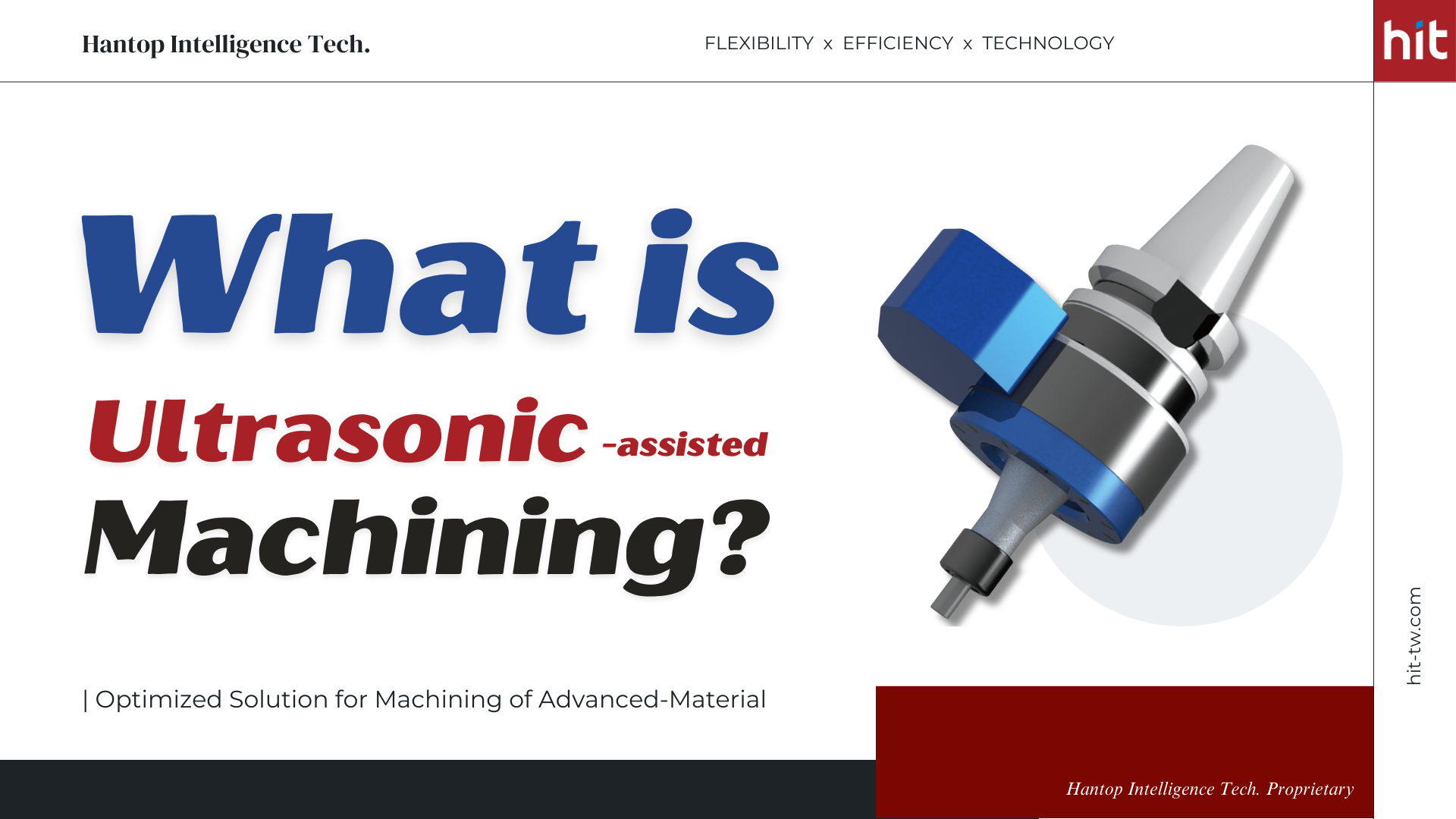
The Working Principle of Ultrasonic-assisted MachiningUltrasonic-assisted Machining is a non-conventional, subtractive manufacturing process that utilizes the power of high-frequency vibraiton to remove material from workpiece. The range of ultrasonic vibration is typically over 20kHz (20,000 oscillations per second), which may be recognized as a silent process since the human ear cannot hear such high frequency.Generally, the ultrasonic power is transmitted via a transducer to the cutting tool, providing the tool with high frequency micro-vibration to facilitate in the milling, drilling, and grinding process. Ultrasonic-assisted machining is mostly used in the machining of advanced materials, which shows most benefits for hard-and-brittle and hard-to-cut materials, such as technical ceramics (Al2O3 / Aluminum Oxide, ZrO2 / zirconium dioxide, SiC / silicon carbide, quartz), optical glass, tungsten carbide, stainless steel, hardened steel, heat-resistant alloy (Ti-6Al-4V / titanium alloy, Inconel 718 / nickel alloy), etc.(Figure 1. rotary ultrasonic machining working principle for material removal, source: Precise Drilling of Holes in Alumina Ceramic (Al2O3) by Rotary Ultrasonic Drilling and its Parameter Optimization using MOGA-II)The high frequency micro-vibration works as a continuous series of hammering action that creates micro-cracks on the workpiece to help with material removal. The surface of the workpiece receives constant strikes from the tool which then builds up stress within the material to a certain point that forms micro-cracks. These micro-cracks allow the material to be easily removed from the workpiece.Therefore, ultrasonic-assisted machining is often used in the machining of micro-features, such as micro-holes (learn more on Ultrasonic-assisted Micro-Drilling of Silicon Carbide), drilling small and deep holes (learn more on Ultrasonic-assisted Deep Hole Drilling of AISI-1045 Carbon Steel), milling tiny internal threads (learn more on Ultrasonic-assisted M2 Internal Threading of Aluminum Oxide), or milling slots with high aspect ratio (learn more on Ultrasonic-assisted Full Slotting of AISI-4140 Alloy Steel).(Figure 2. HIT ultrasonic-assisted machining module serves to provide optimized machining process as a solution to the machining of advanced materials) Unique, Cutting-edge Technology of HIT Ultrasonic-assisted Machining Module HIT Ultrasonic-assisted Machining Module: Product Information [One Set of HIT Ultrasonic Machining Module](Figure 3. HIT ultrasonic-assisted machining module product series collection)One set of HIT Ultrasonic-assisted Machining Module contains: a) an ultrasonic driver b) an ultrasonic toolholder (HBT, HSK, CAT, Grinding Wheel series) c) an ultrasonic power transmitter d) an external control panel.a) Ultrasonic Driver - It is used to generate ultrasonic power and automatically detect proper frequency of vibration for the cutting tools. Its frequency and related information will be displayed on the screen of the external control panel.(Figure 4. HIT ultrasonic-assisted machining module - ultrasonic driver)b) Ultrasonic Toolholder - HIT provides the most common specifications: HBT, HSK, CAT, and Grinding Wheel series of toolholders, which work compatibly well with the majority of spindle types in CNC machining centers.(Figure 5. HIT ultrasonic-assisted machining module - ultrasonic toolholders)c) Ultrasonic Power Transmitter - It will be installed right beside the ultrasonic toolholder to transmit ultrasonic power to the toolholder. There will be a 0.5mm gap in between (the "non-contact" ultrasonic power transmission technology).(Figure 6. HIT ultrasonic-assisted machining module - ultrasonic power transmitter)(Figure 7. actual machining process by using HIT ultrasonic-assisted machining module)d) External Control Panel - Machinists can use this panel to control the driver while the driver being installed inside the control box of the machine tool. Customers can adjust the ultrasonic amplitude by setting the power level percentage according to the target machining material.(Figure 8. HIT ultrasonic-assisted machining module - external control panel) [Schematic Ullustration of Machine Integration]The following shows an illustration of the module and machine integration.(Figure 9. the installation and machine integration of HIT ultrasonic-assisted machining module)Here is a close-up illustration of the installation of ultrasonic power transmitter and ultrasonic toolholder.(Figure 10. the installing position of HIT ultrasonic toolholder and power transmitter with power transmitter jig)The Unique Design in HIT Ultrasonic Technology [Non-contact Ultrasonic Power Transmission]The method or device for transmitting ultrasonic power from the velocity transformer (or transducer) to the cutting tool varies from brand to brand. HIT Ultrasonic Toolholder implements the unique "non-contact (wireless) ultrasonic power transmission" technology, embedded inside with piezoelectric elements that help generate high frequency (20~32kHz) micro-vibration on the cutting tool.(Figure 11. the unique non-contact / wireless ultrasonic power transmission technology developed by HIT)There is a 0.5mm air gap between the ultrasonic power transmitter and the ultrasonic toolholder. This design obviates the need for regular replacement of carbon brushes and conductive slip rings in traditional ultrasonic machining products, which not only adding to the production costs but also limitting the increase of rotation speed. [Automatic Frequency Detection & Flexible Oscillation Amplitude Adjustment]The ultrasonic driver not only works to generate ultrasonic power (output) but also has the capability to detect and search for the proper frequency of the cutting tool (input) by automatic frequency-scan and frequency-lock. Different cutting tools have their corresponding frequency of vibration due to different geometric shapes and tool shank materials. The ultrasonic driver functions to constantly locate the proper frequency for the tool during the machining process, ensuring a stable output-input mutual interaction.(Figure 12. the monitor of external control panel shows the corresponding frequency for the cutting tool detected by HIT ultrasonic driver)Customer can alter the ultrasonic oscillation amplitude by adjusting the Power Level knob on the external control panel (from 0% to 100%). It controls the intensity of ultrasonic oscillation in the axial direction. The intensity of the vibration varies with different targeted machining materials; for instance, the power level is usually set to 80-100% while machining hardened steels or heat-resistant alloys, which are in need of stronger striking force to assist with the cutting.(Figure 13. the ultrasonic oscillation amplitude can be adjusted by using the Power Level knob on the external control panel) [Easy Installation of Module System]This technology, packaged in a module system instead of whole machine, provides easy installation and integration with current CNC machines. The module can be seen as an upgraded program for CNC machines with a more flexible use of space, lower energy consumption, and much lower investment cost. Advantages of HIT Ultrasonic-assisted Machining ModuleThe following illustrates the three main aspects that are mostly recognized as benefits derived from HIT ultrasonic-assisted machining process. (Usually one or two aspects stand out more than the other based on different machining process and purpose.) Higher Machining EfficiencyAs previously mentioned, ultrasonic-assisted machining operates by the mechanism of constantly striking the workpiece with high frequency micro-vibration that creates micro-scale cracks within the material. The micro-cracks allow the material to easily break off from the workpiece, and thus help enhance MRR (Material Removal Rate). The more material to be removed within the same amount of time indicates less total process time required, which brings higher machining efficiency. Longer Tool LifeIn conventional machining, it usually generates high cutting force and cutting heat when dealing with advanced materials, especially when it comes to high hardness materials or specific material properties that creates long, stringy cutting chips. Workpieces made of advanced materials often have strict standards or demands on its quality, which may require specialized or high-end cutting tools. High cutting force / heat can take a toll on the tool life and increase the production cost.With the application of HIT ultrasonic-assisted machining technology, the micro-vibration in axial (Z-axis) direction allows the cutting tool to lift from the workpiece, creating intermittent contact during the machining process. This brings better inflow of cutting fluid, enabling easier removal of cutting chips and cutting heat. Along with better material removal, it helps reduce the cutting force. The lowered cutting force and cutting heat consequently contribute to more stable and longer tool life.(Figure 14. with HIT ultrasonic, the formation of cutting chips is different with much smaller size compared to that without ultrasonic)(Figure 15. with HIT ultrasonic, it brings better ceramic particle flushing which greatly reduces tool wear) Better Workpiece QualityIn the machining of advanced materials, workpiece quality (e.g. micro-hole quality or surface quality) is highly valued and mostly viewed as the critical determining factor in customer placing order.The most distinguished benefit of ultrasonic technology can be seen in the drilling hole quality. With the lowered cutting force, size of edge-cracks can be greatly reduced especially when drilling micro-holes on brittle materials.(Figure 16. with HIT ultrasonic, the size of edge-cracks around exit holes is greatly reduced in micro-drilling of glass material)Another notable advantage is the improvement in surface quality in terms of lower surface roughness and the mitigation of tool marks. The lowered cutting force / heat reduces tool wear and consequently helps moderate the friction between cutting tool and workpiece.(Figure 17. with HIT ultrasonic, the surface roughness is reduced with mitigating tool marks)On the premise of maintaining great workpiece quality and stable tool life, the machining parameters can be further optimized to achieve even higher machining efficiency. All things considered, rather than playing magic tricks, HIT Ultrasonic-assisted Machining Module offers an optimized solution for the machining process of advanced materials, aiming to provide cutting-edge expertise in upgraded process.🔎 Find out more Case Studies on Ultrasonic Machining Technology📺 Check out Videos on Ultrasonic-assisted Machining Process-Hantop Intelligence Tech.Optimized Solution for Machining of Advanced-Material with Ultrasonic-Assisted Machining Module +886-4-2285-0838 sales@hit-tw.com


Using a #80 Φ120mm electroplated diamond wheel with HIT HBT-40 ultrasonic grinding wheel module, we achieved 3.3 times higher MRR (Material Removal Rate) and 3 times longer wheel life versus the baseline CCB (Carbon-Ceramic Brake Disc) rough-grind. With HIT HBT-40 ultrasonic toolholder module and a Φ5mm diamond drill, we saw 5 times faster cycle time, ≤0.1mm crack size, and 4 times longer tool life. Test conditions and parameters are listed in Tables A-D. Why are CMCs hard to machine? 🔘 What material properties drive chipping, fraying, and heat? Low fracture toughness and limited plasticityCMCs (Ceramic Matrix Composites) have low fracture toughness and virtually no plasticity that cause cracks to initiate at small defects instead of forming a continuous shear chip.(Figure 1. fragment of sports car carbon-ceramic discs brakes) High hardness and abrasive ceramic phasesTheir very hard, abrasive phases (e.g., SiC, Al2O3) intensify tool wear and frictions, which concentrates heat at the tool-workpiece interface. Heterogeneous and anisotropic architectureThe heterogeneous fiber structure indicates unstable cutting force during processing; weak fiber-matrix interfaces bring potential interfacial debonding, so edges fuzz and fray rather than cut cleanly. Thermal properties that localize heatMany matrices have modest thermal conductivity, which easily builds up cutting heat in within. Heat concentrates at the tool-workpiece interface, raising wear and burn risk. Oxidation sensitivityAt temperature, oxidative embrittlement of carbon-containing phases further reduces toughness and accelerate edge chipping. 🔘 Where do conventional grinding and drilling fail on CMCs? Long process time with heat generation that seriously consumes wheelsGrinding of CMCs runs slow and eats wheels because the ceramic phases are very hard and abrasive, so diamond grains dull and pull out quickly. As a result, the depth of cut and feed should remain low to avoid brittle fracture and heat. Hardness of the material brings excessive heat generation during processing. The wheels wear out quickly and force more dress cycles, so material removal rate stays low, while wheel consumption stays high. Long process time, poor hole quality, and serious tool wearDrilling of CMCs takes long, cracks the hole edges, and burns tools mainly because of its high hardness and heterogeneous structure. The cutting lips see continuous hard-abrasive contact that strips diamond coatings fast. To prevent cracks around the drilling holes, efficiency usually must be sacrificed, which extends cycle time further. How does HIT Ultrasonic improve CMC machining? 🔘 What is the ultrasonic mechanism in grinding and drilling? Ultrasonic mechanism in grinding processUltrasonic provides high frequency micro-scale vibrations (over 20,000 times per second in axial direction) to the grinding wheel. The vibration periodically separates wheel and workpiece during processing, turning conventional rubbing into micro-impacts, which facilitates in massive material removal. The periodic separation also pumps cutting fluid into the interface, which helps with wheel cooling and cutting chip evacuation.(Figure 2. HIT ultrasonic-assisted surface grinding of carbon-ceramic brake disc) Ultrasonic mechanism in drilling processThe percussive micro-cutting from ultrasonic micro-vibrations initiates micro-fracture in brittle phases, so material removal shifts from crushing to controlled chip or powder formation. Short contact times and better fracture mechanics reduce frictional heating, which allows coolant for easier inflow to the interface. 🔘 Methods and results in HIT ultrasonic grinding of CMC Table A. Ultrasonic Grinding of CMC: Machining Information Material Carbon-ceramic (C/SiC) brake disc Feature Surface grinding (roughing) Toolholder HBT-40-W01 ultrasonic grinding wheel toolholder Wheel Selection #80 Φ120mm electroplated diamond wheel [Surface Grinding of Carbon-Ceramic Brake Disc (CCB)] Machining Methods Table B. Parameters (Conventional vs. Ultrasonic) Spindle Speed(S: rpm)Feed Rate(mm/min) Radial Depth of Cut (Ae: mm) Axial Depth of Cut (Ap: mm)UltrasonicPower Level(%)HITUltrasonic5,9521,200200.020100Original Process9000.008- HIT ultrasonic provides high frequency micro-vibrations to the grinding wheel, which intermittently impacts the workpiece during processing, creating space for cooling and chip removal, helping to reduce grinding force.The reduction in grinding force allows for increased feed rate and depth of cut per pass, achieving an overall 3.3 times improvement in material removal rate (MRR). Along with effective cooling and improved chip removal of the grinding wheel, HIT ultrasonic helps to extend the wheel life by 3 times. [Surface Grinding of Carbon-Ceramic Brake Disc (CCB)] Machining Results Table C. Results - Higher MRR & Longer Wheel Life with Ultrasonic Material Removal Rate(mm3/min)Wheel Life(pcs/per wheel)HIT Ultrasonic4803Original Process1441(Figure 3. HIT ultrasonic-assisted surface grinding of carbon-ceramic brake disc brought 3.3x higher material removal rate)(Figure 4. HIT ultrasonic-assisted surface grinding of carbon-ceramic brake disc brought 3x longer wheel life)🧠 Learn more about this case study at Surface Grinding of Carbon Ceramic Brake Disc (CCB)🔘 Methods and results in HIT ultrasonic drilling of CMC Table D. Ultrasonic Drilling of CMC: Machining Information Material Carbon-ceramic (C/SiC) brake disc Feature Φ5 x 5mm (blind holes) *aspect ratio: 1x Toolholder HBT-40 ultrasonic toolholder Tool Selection Φ5mm diamond drill [Drilling of Carbon-Ceramic Brake Disc (CCB)] Machining Methods Table E. Parameters (Conventional vs. Ultrasonic) SpindleSpeed(S: rpm)Feed Rate(mm/min)Q-peckdrilling(mm)Axial Depth of Cut(Ap: mm)Ultrasonic Power Level(%)HITUltrasonic 4,000~6,500 2~8 0.16~1.00 2.5~550Original Process4,00010.045- During HIT ultrasonic machining, the tool intermittently impacts the workpiece, creating space for cooling and chip evacuation, which helps reduce drilling force.The reduction in drilling force allows for optimization of machining parameters, effectively shortening the process time per hole and achieving 5 times higher machining efficiency.The tool’s impact on the workpiece became smaller yet more frequent, significantly decreasing the size of edge-cracks around the drilled holes. This led to 5 times better hole quality.Compared with the process without ultrasonic (using the same optimized parameters), the number of drilling holes completed per tool increases, and the overall tool life is extended by 4 times. [Drilling of Carbon-Ceramic Brake Disc (CCB)] Machining Results Table F. Results - Higher Efficiency, Cleaner Holes, Longer Tool Life with Ultrasonic Process Time(min/per hole)Size of Edge-Cracks(mm)Number of Drilling Holes(holes/per tool)HIT Ultrasonic30.112Original Process150.53(Figure 5. HIT ultrasonic-assisted drilling of carbon-ceramic brake disc brought 5x higher machining efficiency)(Figure 6. HIT ultrasonic-assisted drilling of carbon-ceramic brake disc brought 5x better hole quality)(Figure 7. HIT ultrasonic-assisted drilling of carbon-ceramic brake disc brought 4x longer tool life)🧠 Learn more about this case study at Drilling of Carbon Ceramic Brake Disc (CCB) Where is ultrasonic CMC machining used in industry? 🔘 Carbon-Ceramic Brake Disc (CCB) in Motorsports Industry(Figure 8. carbon-ceramic brake discs are widely used in motorsports industry, photo by Gemanis Industries LLC)Carbon-ceramic (C/SiC) brake discs (CCB) are used in GT and endurance racing for their low mass, high stiffness, and exceptional fade resistance at sustained temperatures beyond iron rotors. Less mass means better turn-in, quicker response, and steadier pedal over long stints. Their ceramic matrix resists oxidation and wear far better than carbon-carbon in wet or mixed conditions. However, they need proper warm-up and pad bedding, are sensitive to impact and thermal shock, and can carry high cost. Teams use them when durability and consistency matter more than upfront price. 🔘 Aircraft Brackets in Aerospace Industry(Figure 9. generated image by AI shows simulation of aircraft brackets made of CMC used in aerospace industry) Ceramic matrix composites are used for aircraft brackets that sit near hot zones—engine nacelles, exhaust ducts, thermal shielding—where metal brackets creep or oxidize. CMC brackets cut weight, keep stiffness at high temperatures, and hold shape due to low thermal expansion and good oxidation resistance. They also isolate heat into the stack, reducing thermal growth loads on fasteners and skins. However, they bear higher cost, notch sensitivity, and tight machining tolerances. FAQs on Ultrasonic CMC Machining 🔘 Q1. What diamond grits and bonds suit CMC grinding for high MRR?Use coarse diamond with the grits size ranging from #60~#120 wheel for massive material removal roughing process. Start at #80 for roughing and move finer only if edge quality demands it. The electroplated diamond grinding wheel is recommended for maximum bite and short-to-medium runs. Pair it with ultrasonic grinding technology to reduce grinding force and improve cooling and chip evacuation. The parameters can be further optimized with higher material removal rate (MRR). 🔘 Q2. What amplitude works for CMC drilling?For CMC drilling process, 100% ultrasonic power level (approximately 15µm amplitude) is often too aggressive and raises micro-chipping and cracks around drilling holes. With HIT ultrasonic drilling technology, it delivers intermittent contact and fracture-assisted cutting without over-impact. It also keeps thrust and torque low, which limits the edge damage. It is suggested to use around 50% ultrasonic power level on carbon-ceramic brake disc (CCB) for drillings holes in heterogeneous CMCs.💡 Learn more about HIT Ultrasonic Process Solution for machining of advanced-materials (ceramics, quartz, glass, ceramic matrix composites, etc.):Rough Grinding of Aluminum Silicon Carbide (AlSiC) as Flip-Chip LidMicro-Drilling of Silicon Carbide (SiC)Curved Surface (Rough) Grinding of Silicon Carbide (SiC)(Helical) Circular Ramping of Silicon Carbide (SiC)Surface Grinding of Silicon Carbide (SiC) with D100-Grinding Wheel ToolholderMicro-Drilling of Aluminum Oxide (Al2O3) CeramicProfile Grinding of Aluminum Oxide (Al2O3) Ceramic(Rough) Side Grinding of Quartz Glass with D80-Grinding Wheel ToolholderSide Grinding (with Polar Coordinates Programming) of Quartz GlassMicro-channel Trochoidal Grinding of Quartz GlassSoda-Lime Glass: Micro-DrillingMicro-Drilling of AISI-304 Stainless Steel Through Holes on curved surfaceMicro-Milling & Micro-Drilling of AISI-420 Stainless Steel📖 References: Machining of ceramic matrix composites: Challenges in surface integrity by Venkata Kanaka Srivani Maddala and others from Materials Today: Proceedings JournalThe new challenges of machining Ceramic Matrix Composites (CMCs): Review of surface integrity by Oriol Gavalda Diaz and others from International Journal of Machine Tools and ManufactureThe Pros & Cons of Advanced Ceramics by Julie Sullivan from MSC Industrial Direct Co., Inc.Ceramic Matrix Composites by BCC Publishing from BCC ResearchCeramic Matrix Composites Offer Lighter, More Durable Engine Parts by Pratt & Whitney (P&W) from SAE Media GroupArris Composites, Airbus collaborate on composites research for lightweighting cabin brackets by Grace Nehls from CompositesWorldBrake Designs For Cars, What Do They Mean? by Mike G from Gemanis Industries LLCStudy of the machining quality of CMC ceramic composite during high-speed grinding by D.S. Rechenko and R. U. Kamenov from Journal of Physics: Conference Series-Hantop Intelligence Tech.✨Ultrasonic Process Solution for Advanced Materials✨☎️ +886-4-2285-0838📧 sales@hit-tw.com
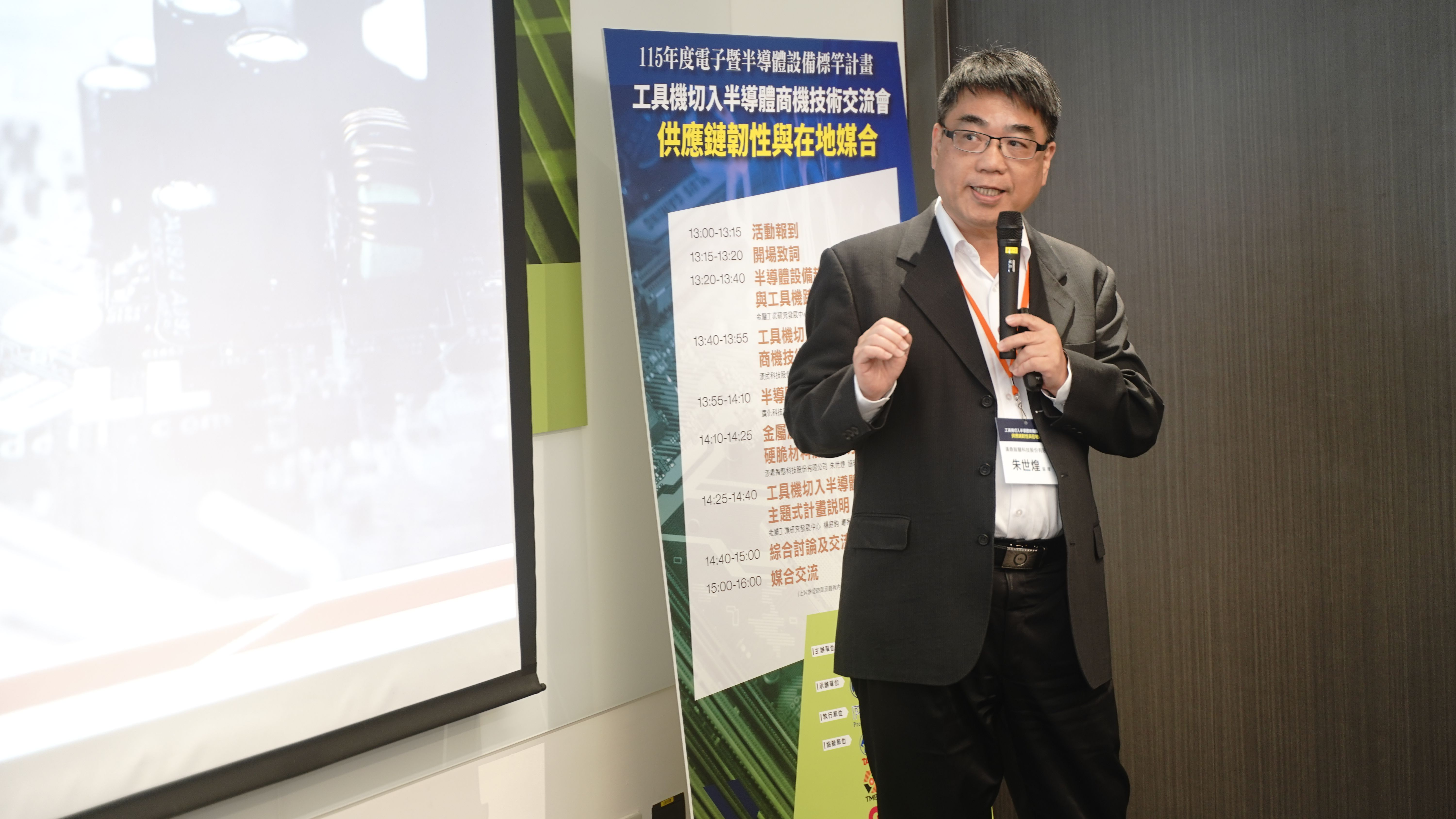
Figure 1. Group photo of the Government officials and industry leaders. During the Taiwan International Machine Tool Show (TMTS 2026), held grandly for the first time at the Taichung International Exhibition Center this year, Hantop Intelligence Tech was invited to participate in a technical seminar event hosted by the Ministry of Economic Affairs of Taiwan (MOEA), and the Precision Machinery Research and Development Center (PMC). This event brought together leaders across the semiconductor industry to deliver keynote speeches. The event was highly anticipated and the venue was fully packed with experts from all over the world.Mr. Shih-Huang Chu, Senior Director of Hantop Intelligence Tech, was invited to deliver a keynote speech titled "Transitioning from Metal to Ceramic and Hard-Brittle Material Machining," addressing the current transition challenges faced by the machining industry. Through case studies of one of our major clients, he provided an in-depth analysis of how traditional metal machining companies successfully capitalized new supply chain business opportunities in the semiconductor and AI era by introducing Hantop's Ultrasonic Technology! The Crossroads of Traditional Precision Machining: Embracing the AI Chip OpportunityIn recent years, the precision machining industry has faced immense challenges. Market competition is intensifying, and the profit margins are gradually shrinking to suffocating levels. Amid the surging demand for AI chips, many machining factories have shifted their focus to high-end materials required for semiconductor equipment and advanced packaging, securing new orders for "semiconductor-grade ceramics. "! The Invisible Hero Behind AI Computing Power: Why Ceramic? As the performance of AI chips driven by leading companies like NVIDIA continues to double, advanced packaging technologies (such as CoWoS, CPO, etc.) and thermal management have become the critical factors determining whether computing power can be stably exerted.Key Indicator 1: The Extreme Demand for Coefficient of Thermal Expansion (CTE)When facing the extreme high temperatures and plasma environments of AI chips, traditional metal materials are often limited by mismatched Coefficients of Thermal Expansion (CTE) or poor corrosion resistance, which can severely shorten the lifespan and cause damage and failure to precious AI chips.Key Indicator 2: Material Stability in Harsh EnvironmentsTherefore, silicon carbide (SiC), aluminum oxide (Al2O3) ceramics, and composite materials like aluminum silicon carbide (AlSiC), which possess excellent thermal properties and stability, have become the top choices for AI chip heat dissipation substrates, test fixtures, and semiconductor equipment components. This wave has brought new opportunities to the precision machining industry, but it has also introduced entirely new challenges. Figure 2. Senior Director Shih-Huang Chu delivered the keynote speechWith Great Opportunity Comes Challenges: Why is Ceramic So Difficult to Handle? However, with great opportunity comes great challenges.Case Study: A Story of Blood, Toil, Tears and SweatDirector Chu shared a case study during his speech: In early 2025, a machining factory specializing in "Metal Heat Dissipation Plates" actively sought transformation as it faced “Red Ocean” competition with declining gross margins. In the second half of the year, they finally managed to secure a sampling order for ceramic materials, only to fall into months of painful trial and error. "They cross-tested all the cutting tools and other key parameters relentlessly, but the results were constant failures," Director Chu mentioned. The most common situations were: severe chipping on the ceramic edges and severe tool wear.The Fundamental Difference in Material Properties: Hardness vs. Fracture ToughnessThe scientific reason behind lies in the huge difference in material properties: ceramics have very high hardness but low fracture toughness. If you approach it with the traditional metal "cutting" mindset, it's like a collision course—it breaks upon contact. This forced them to undergo its first paradigm shift: transitioning from the "removal" to the "brittle abrasive" mechanism, changing from cutting to micro-grinding.Table 1. Comparison of Material Hardness and Fracture ToughnessMaterialMohs HardnessFracture Toughness (Mpa*m^1/2)DescriptionDiamond 10 (Maximum) Very Low (1.5 ~ 5) The hardest but also very brittle. Capable of cutting all materials, but highly susceptible to "brittle fracture" (chipping) when subjected to vibration or impact.SiC, Al2O3,Tungsten Carbide(WC) 9 ~ 9.5 (Very High) Extreme Low (Approx. to 0) Extremely high hardness and shatters easily upon impact. Similar to glass or ceramic, it is difficult to machine and typically requires ultra-hard cutting tools.Hardened Steel, Chromium (Cr) 8 ~ 8.5 (High) Moderate Possesses both a certain level of hardness and the basic toughness of metal; more difficult to cut than general steel. General Steel(e.g., SUS Stainless Steel) 4 ~ 5 (Moderate) Very High (200+) Extremely tough. It will dent and deform under heavy impact but is not prone to complete fracture; it is the most common engineering material. Aluminum (Al) 3 (Low) High Soft in texture with good ductility and toughness; relatively easy to cut and machine.Figure 3. Explanation of the differences in characteristics between hard-brittle materials and traditional metal materials. The Devil is in the Details: Why Changing to Diamond Tools is Not Enough?Many business owners believe that replacing their tools with diamond grinding pins can solve the problem, but in actual combat, they encounter a more hidden challenge.The Hidden Challenge: Powder AdhesionThe client found that after switching to diamond tools, it seemed to be alright at the first glance, but after a few runs, it started to go wrong again. Upon removing the tool, they discovered that the finely ground ceramic powder was firmly stuck to the diamond particles. When the diamonds are covered by powder and their exposure is insufficient, the tool completely loses its grinding ability. This is exactly the core reason why "just changing the tool is not enough; a new method must be introduced: Ultrasonic Technology."Solving New Problems Requires New Methods and a "Paradigm Shift" To successfully enter the field of hard-brittle materials, challengers must undergo a complete paradigm shift:Shift in machining methods: From traditional "cutting" to "grinding".Shift in tool selection: From general-purpose tungsten carbide tools, a full upgrade to "diamond tools".Shift in material machining concept: From the "removal" to the "brittle abrasive" mechanism adapted for hard-brittle materials. In this process, how to balance machining efficiency and cutting force, while perfectly controlling surface quality and suppressing material cracks, has become the decisive task for improving yield rates.Hantop's Solution: The "Self-Sharpening" Magic of Ultrasonic TechnologyTo solve the problems of powder adhesion and machining efficiency, the client ultimately introduced Hantop's ultrasonic-assisted machining module.Revolutionary Breakthroughs Driven by 20,000+ High-Frequency Micro-VibrationsThrough high-frequency micro-level vibrations of over 20,000 times per second, it brought a revolutionary breakthrough to the machining process:Breakthrough 1: Tool Self-SharpeningThe microscopic mechanism generated by high-frequency vibration can shake off the underlying binder, allowing new diamond particles to be continuously exposed, ensuring the tool always remains in its sharpest state.Breakthrough 2: Smooth Chip RemovalThe vibration mechanism can effectively shake off and carry away the ceramic powder, avoiding scratches on the workpiece and completely solving the downtime problem caused by powder adhesion.Breakthrough 3: Stress Elimination and Resistance Reduction Significantly reduces cutting resistance and residual stress, minimizing the incidence of ceramic edge cracks.Figure 4. The principles of ultrasonic-assisted machining. The Invisible Key to Successful Transition: The Entrepreneurial SpiritThe Determination to Believe You Can Do ItAt the end of the speech, Director Chu emphasized that technical equipment is just a tool, and the true key to a successful transition lies in the "Entrepreneurial spirit of believing you can do it." The road to ceramic machining will inevitably encounter challenges, but for those business owners who view problems as a "necessary process" and actively seek solutions, it is only a matter of time.Seamless Upgrades for Existing Machines to Achieve Dual-CapabilityThe role of Hantop Intelligence Tech is to provide the most stable ultrasonic modules that are compatible with over 90% of CNC machine brands, allowing business owners to smoothly upgrade without investing in costly specialized equipments, realizing a multi-capable production line that "can handle both hard-brittle materials and metals." On the path to the high-value-added semiconductor and AI market, we back you.Let us help you overcome the threshold of hard-brittle material machining through technology upgrades, accurately positioning you into the global AI supply chain! Figure 5. Examples of machine tool brands compatible with Hantop's ultrasonic-assisted machining module. 📧Contact Us: Consult on ultrasonic solutions for hard-brittle materials! 💡Click here to learn about more cases💡 💡Click here to request for product catalog💡 TEL:+886-4-2285-0838EMAIL:sales@hit-tw.com
We use cookies to optimize and continuously update it according to your needs.The settings can be changed at any time under "Privacy"
