
 TMTS Virtual Application
Where Does Tool-Change Time Actually Go? Choosing an Unclamping Solution by Spindle Type
Tool-change time is often treated purely as a tool-magazine speed problem. In practice, the response time of the unclamping action itself is frequently one of the decisive factors in reducing tool-to-tool time.
1. Start with the spindle type, not the tonnage
The first decision point when selecting an unclamping mechanism is not force rating — it is spindle type:
| Spindle type | Solution | How it acts |
|---|---|---|
| Belt-driven spindle | Air-oil booster unclamping cylinder (e.g. BPT series) | Cylinder acts directly on the spindle head |
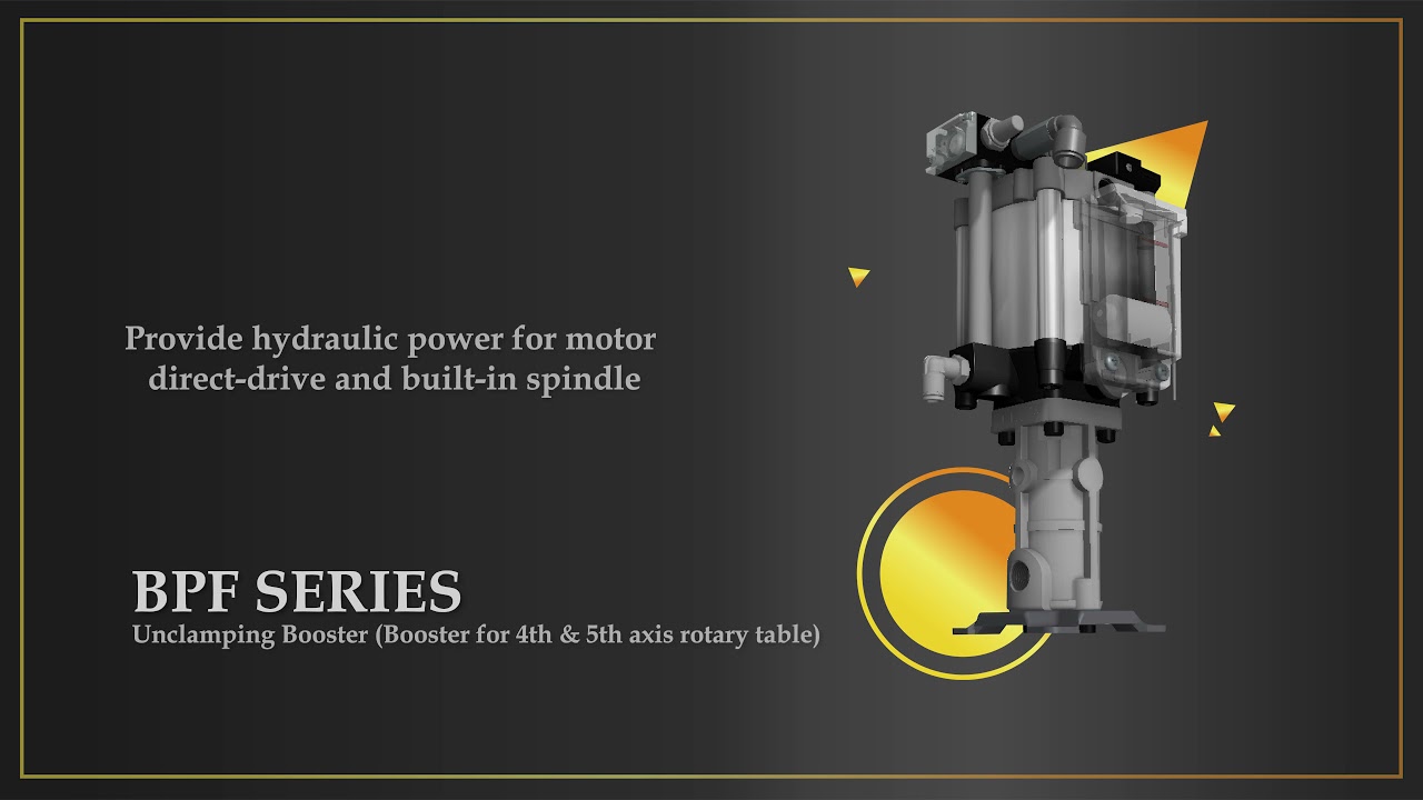
| Direct-drive / built-in spindle | Air-oil booster hydraulic power unit (e.g. BPF series) | Supplies hydraulic power to an external unclamping cylinder |
Belt-driven spindles typically leave enough space above the spindle head for a cylinder to be mounted and act directly. Direct-drive and built-in motor spindles, constrained by their structure, generally require an external hydraulic power source driving a separate unclamping cylinder. This distinction governs the rest of the configuration.
2. Booster unclamping cylinder: where the time goes
- Unclamping response time — the air-oil boosting stroke design translates directly into unclamping seconds. HINAKA BPT unclamps in 0.17 s, with tool change completed in under one second (approx. 0.98 s for BT30, 1–1.2 s for BT40).
- Modular piping — integrating the control valve into the rear cover with built-in piping raises air flow while cutting on-site piping labour and assembly cost.
- Lightweight body — an aluminium cylinder body reduces Z-axis load, directly affecting ball-screw and guideway life; this matters most on machines with high tool-change frequency.
- Dual position sensing — clamp/unclamp states need accurate feedback. Insufficient sensing accuracy shows up as conservative tool-change timing in the control program.
- Built-in air-blow cleaning — an integrated blow function removes the need for an external air-blow valve, eliminating one failure point.
3. Booster hydraulic power unit: reliability over raw speed
For direct-drive and built-in spindles, the priorities shift toward hydraulic cleanliness and predictability:
- Seamless aluminium-alloy oil chambers — prevent iron shavings from entering the hydraulic system and damaging spindle components, one of the most expensive failure modes on built-in spindles.
- Oil-level monitoring — a transparent, corrosion-resistant reservoir with internal float and external sensor gives warning before low oil causes downtime or a collision.
- Mounting flexibility — standard vertical and standard horizontal configurations to suit the machine layout.
4. Information to prepare before selection
- Spindle type (belt-driven / direct-drive / built-in)
- Tool holder specification (BT30 / BT40 / BT50 or other)
- Required unclamping force and stroke
- Available mounting space above the spindle head
- Target tool-to-tool time
- On-site air supply conditions
Faster tool change is rarely a single-component specification race. It comes from the fit between spindle type, unclamping mechanism, sensing feedback and piping design.
HINAKA FLUID POWER has focused on hydraulic and pneumatic components for machine tools since 1988, with more than 50 patents worldwide, covering fluid power solutions from spindle to tool magazine.
MAKTEK Eurasia 2026: Sep 28 – Oct 3, 2026, Tüyap Fair and Congress Center, Istanbul | Hall 6, Booth 607B / 607C
Website: www.hinakaorg.com