
 TMTS Virtual Application
Products







more
CAMPOWER INTL. Precision Machinery Co., Ltd. is proud to announce that it has received the Gold Label in the Enterprise AI Empowerment Category of the 2nd Machine Tool Industry AI Empowerment Label Program, recognizing the company's achievements in artificial intelligence adoption, R&D process optimization, and digital transformation.As the machine tool industry continues to embrace smart manufacturing and digital innovation, CAMPOWER remains committed not only to advancing its core roller cam technology but also to integrating AI into its internal operations.Through the development and implementation of its AI-Powered R&D Work Platform, CAMPOWER has established a more efficient, transparent, and collaborative R&D environment, strengthening its technological capabilities and operational competitiveness.AI-Powered R&D Work Platform: Enhancing Efficiency and CollaborationTo address traditional challenges such as fragmented communication, limited project visibility, and time-consuming technical information retrieval, CAMPOWER has implemented an integrated AI-powered R&D management platform.The platform combines several key functions:Intelligent Project Management: Centralizes R&D projects and task assignments, enabling managers to monitor project progress and team responsibilities in real time.Gantt Chart Scheduling: Provides visualized project timelines, task assignments, and progress tracking to improve coordination and workflow efficiency.AI R&D Assistant: Supports daily documentation, information analysis, and technical inquiries, reducing repetitive administrative tasks.Intelligent Knowledge Base: Integrates technical documents and product catalogs, enabling AI-assisted information retrieval and more efficient knowledge sharing.Automated Weekly Reports: Generates project progress reports based on updated task information, minimizing manual reporting efforts.By integrating these capabilities into a unified platform, CAMPOWER has transformed conventional R&D management into a more streamlined, data-driven workflow.Measurable Improvements Through AI ImplementationCAMPOWER's AI initiative goes beyond technology adoption, delivering measurable improvements in daily R&D operations.Key achievements include:Real-Time Project Visibility: Project status updates that previously required approximately half a day can now be accessed instantly.60% Reduction in Information Gathering Time: AI-assisted knowledge retrieval significantly reduces the time required to locate technical information.One-Third Reduction in Task Assignment Time: Digital task management streamlines communication and reduces administrative delays.Improved Team Collaboration: Centralized information sharing minimizes communication gaps and enhances project coordination.In addition, CAMPOWER utilizes locally deployed AI models and an internally managed knowledge base to support information security, technical knowledge retention, and controlled data access.These improvements demonstrate how AI can deliver practical value to precision machinery manufacturers by optimizing internal processes and strengthening organizational efficiency.Advancing Toward Smarter Manufacturing and Sustainable InnovationReceiving the Gold Label in the Enterprise AI Empowerment Category represents an important milestone in CAMPOWER's digital transformation journey.The recognition reflects the company's commitment to applying AI technologies in practical business operations while continuously improving its engineering and manufacturing capabilities.Looking ahead, CAMPOWER will continue expanding AI applications, strengthening R&D knowledge management, and enhancing cross-departmental collaboration.By combining AI-driven operational innovation with its expertise in multi-lead roller cam technology and high-precision rotary tables, CAMPOWER aims to further strengthen its global competitiveness and deliver greater value to machine tool manufacturers and precision machining industries worldwide.CAMPOWER — World Leader in Cam TechnologyPrecision is Never an Option — It's Our Standard.
/ 10. 08. 2026
more
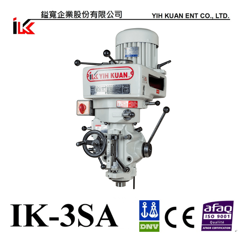
Exhibition: VIMF 2026 – Vietnam Industrial & Manufacturing Fair, Bac NinhDate: November 4–6, 2026Venue: Kinh Bac Cultural Center, Bac Ninh, VietnamBooth: 691 Northern Vietnam has become an important manufacturing hub for electronics, automotive parts, metalworking, machinery, and industrial supply chains, with Bac Ninh playing a key role in the region’s continued industrial development.VIMF Bac Ninh focuses on industrial manufacturing, automation, metalworking, machinery, and smart manufacturing solutions, providing an important platform for manufacturers to explore new equipment, improve production efficiency, and build new business partnerships.With nearly 50 years of experience in milling head manufacturing, YIH KUAN provides a wide range of solutions including plano milling heads, CNC milling heads, vertical turret milling heads, angle heads, and special-purpose milling heads.In addition to supplying machine tool builders and special-purpose machine manufacturers, YIH KUAN also supports existing machine upgrades through milling head replacement, machine retrofit solutions, flange and interface design, and machining application evaluation.For manufacturers looking to extend machine service life, improve machining capability, or develop new machines and special-purpose applications, YIH KUAN can recommend suitable milling head solutions based on machine type, workpiece material, spindle speed, cutter size, and mounting interface.We warmly welcome you to visit our booth and discuss your machine upgrade, milling head selection, and machining application requirements with us.
YIH KUAN
/ 10. 06. 2026
more
This year, YIH KUAN will be presented at two partner booths during METALEX 2026.Exhibition: METALEX 2026Date: November 18–21, 2026Venue: BITEC, Bangkok, ThailandMeet YIH KUAN at:Booth AL01|PMC – Precision Machinery Research & Development CenterBooth BS29|SAHAMIT MACHINERY PUBLIC CO., LTD. METALEX is one of Southeast Asia's major exhibitions for metalworking, machine tools, manufacturing technologies, automation, and industrial solutions. It provides an important platform for manufacturers across Thailand and Southeast Asia to explore new technologies, equipment upgrades, machining solutions, and business partnerships.With nearly 50 years of experience in milling head manufacturing, YIH KUAN provides a wide range of products including plano milling heads, CNC milling heads, vertical turret milling heads, angle heads, and special-purpose milling heads.In addition to supplying machine tool builders, YIH KUAN also supports machine retrofit companies and special-purpose machine manufacturers with milling head selection, machine upgrade solutions, flange and interface design, and machining application evaluation.As Thailand continues to develop its automotive parts, mold and die, metalworking, and industrial manufacturing sectors, YIH KUAN looks forward to connecting with more local manufacturers at METALEX 2026.Whether you are planning to improve an existing machine, develop a new machine, or solve a special machining application, our team can recommend suitable milling head solutions based on machine type, workpiece material, spindle speed, cutter size, and mounting interface.We warmly welcome you to visit us and discuss your milling head, machine retrofit, new machine, and special machining requirements.
YIH KUAN
/ 10. 06. 2026
more
Exhibition Date | October 20–22, 2026Venue | Taichung International Convention and Exhibition CenterBooth No. | E102DAIKEN TOOLS × YIH KUAN ENTERPRISEFrom every hand tool used on the shop floor to every machining and inspection process, we work together to help manufacturers stay in control of every critical detail.In manufacturing, no tool plays a minor role.A reliable hand tool affects operational efficiency, safety, and consistency.A stable milling head determines machining performance and precision.Accurate measuring and inspection equipment helps manufacturers monitor production data, machine conditions, and quality details throughout the process.From assembly, adjustment, and maintenance to machining and inspection, every tool and every process contributes to achieving high-quality manufacturing.At 2026 Taiwan International Tools & Hardware Expo × International Hardware Expo Taiwan (TiTE × IHT), DAIKEN TOOLS will showcase its professional pliers and hand tools together with YIH KUAN ENTERPRISE, presenting a complete manufacturing perspective covering:Professional Hand Tools × Machine Tool Components × Production Inspection► DAIKEN TOOLSSince 1968, DAIKEN TOOLS has specialized in the development and manufacturing of professional pliers and hand tools.Its product range includes VDE insulated pliers, high-leverage pliers, automotive service pliers, precision electronic pliers, special-purpose pliers, and cable cutters, along with OEM and ODM services.With products supplied to more than 50 countries worldwide, DAIKEN TOOLS responds to the practical needs of different industries through professional design, rigorous inspection, and reliable durability.► YIH KUAN ENTERPRISESince 1977, YIH KUAN has been dedicated to the machine tool industry, specializing in professional milling heads and measuring and inspection equipment.Our milling head solutions include turret milling heads, gantry milling heads, CNC gear heads, and angle heads. We also provide solutions for new machine integration, existing machine upgrades, and customized applications.Through measuring and inspection equipment, we further help manufacturers monitor machine conditions, production data, and quality details—ensuring that machining performance is not only stable, but also accurately verified.One company focuses on professional tools in the hands of skilled operators.The other focuses on the core of machine tools and extends its expertise into production inspection.Coming from different fields of expertise, we share the same goal: improving every stage of the manufacturing process.“From professional hand tools to machine tool components and precision inspection, we help manufacturers take control of every detail and achieve greater precision in production.”We sincerely invite you to visit us at Booth E102 and discover the strength of Taiwanese manufacturing in professional hand tools, milling heads, machine upgrades, and production inspection solutions.TiTE 2026 × IHT 2026#DAIKENTOOLS#YIHKUAN #MillingHead#ProfessionalTools #Pliers #MachineTools #MillingHead #InspectionEquipment #TaiwanManufacturing
YIH KUAN
/ 09. 22. 2026
more
How to Choose an Angle Head? Manual or Automatic Is Only Part of the DecisionThe right choice depends on how you cut — not just how you operate.When selecting an angle head, one of the first questions many customers ask is:“Is it manual or automatic?”The operating method is certainly important. However, an angle head is ultimately a machining tool, and the right selection depends on much more than its level of automation.Workpiece material, cutter diameter, spindle speed, cutting load, machine conditions, and the frequency of angle changes should all be considered.At YIH KUAN, we believe the selection process should follow a simple principle:First, make sure it can handle the cutting. Then decide how you want to operate it.Start with the Cutting RequirementsBefore comparing manual, semi-automatic, and fully automatic angle heads, several basic machining conditions should first be confirmed:Workpiece Material | Cutter Diameter | Spindle Speed | Depth of Cut | Width of Cut | Feed Rate | Machine Power | Spindle InterfaceFor example, machining aluminum with a Ø30 mm cutter and machining tool steel with a Ø150 mm face mill can require very different angle head specifications.No matter how advanced the automation system is, if the speed range, structure, or cutting capability does not match the actual machining requirements, it may not be the right solution.Higher RPM Is Not Always BetterSome angle heads on the market emphasize spindle speeds of 6,000 rpm, 8,000 rpm, or even higher.High-speed angle heads have clear advantages when using smaller cutters, performing high-speed machining, or working under conditions that require higher cutting speeds.However, when larger cutters are used, steel is being machined, or heavier cutting loads are involved, maximum spindle speed should not be the only consideration.Other factors such as torque requirements, structural rigidity, cutter size, and cutting load become equally important.High speed is one type of capability. Torque, rigidity, and the ability to withstand cutting loads are also essential machining capabilities.Neither approach is inherently better. They are designed for different machining requirements.Why Does YIH KUAN Focus on 800–2,000 rpm?YIH KUAN angle heads are primarily designed for BT50 / NT50 machine applications, with spindle speeds mainly ranging from 800 to 2,000 rpm.If maximum spindle speed alone is compared, these are not high-speed angle heads designed to reach 6,000–8,000 rpm.That is because our product focus is different.YIH KUAN angle heads are designed with an emphasis on larger cutters, low-to-medium spindle speeds, higher torque requirements, structural rigidity, and heavier cutting applications.For applications such as machining the sides of large workpieces, cutting steel, or using larger face mills, the key question is often not:“What is the maximum RPM of this angle head?”but rather:“Is this angle head suitable for my cutter and actual cutting conditions?”Manual, Semi-Automatic, and Fully Automatic Angle Heads: What Is the Difference?Once the required cutting capability has been confirmed, the next step is to determine the appropriate operating method.Manual, semi-automatic, and fully automatic angle heads should not simply be viewed as “basic, intermediate, and advanced” options.Each is designed for different machining frequencies, operating requirements, machine configurations, and levels of automation.ComparisonManual Angle HeadSemi-Automatic Angle HeadFully Automatic Angle HeadAngle Head InstallationManualManualAutomatic / Depends on system designClampingManualManualAutomatic / Depends on system designAngular Rotation / IndexingManualAutomaticAutomatic / Depends on system designOperator InvolvementHigherMediumLowAngle Change EfficiencyStandardHighHighSystem ComplexityLowMediumHighMachine Integration RequirementsLowMediumHighInitial InvestmentLowerMediumHigherRetrofit FlexibilityHighHighDepends on machine configurationBest Suited ForInfrequent angle changesFrequent angle changes after installationHighly automated, continuous productionAvailable from YIH KUAN✓✓—Note: Definitions of semi-automatic and fully automatic angle heads may vary among manufacturers. At YIH KUAN, a semi-automatic angle head refers to manual installation/clamping combined with automatic angular rotation/indexing.Manual Angle Head: Simple, Direct, and Flexible for Retrofit ApplicationsWhen the machining direction remains relatively fixed, or the angle only needs to be changed occasionally, a manual angle head can often meet the requirement effectively.The operator manually installs and clamps the angle head, sets the required machining angle, and then begins machining.This approach requires less system integration and provides excellent flexibility for existing machines.For existing gantry milling machines, boring mills, and other large machine tools, a manual angle head can be a practical way to add side machining or special-angle machining capability without making extensive modifications to the original machine.Semi-Automatic Angle Head: Automating the Action That Happens Most OftenAt YIH KUAN, a semi-automatic angle head does not mean automatic head changing.The angle head is still manually installed and clamped by the operator. Once installed, however, angular rotation/indexing can be performed automatically.Manual Clamping + Automatic Angular RotationThis design is particularly suitable when the angle head remains installed on the machine, but the machining direction needs to be changed frequently during the machining process.In this situation, the repetitive action is not changing the entire angle head.It is changing the machining angle.By automating the action that occurs most frequently, a semi-automatic angle head can provide a practical balance between machining efficiency, system complexity, and investment cost.Fully Automatic Angle Head: Designed for Highly Automated ProductionFully automatic angle head systems become more valuable in high-volume production, unattended machining, or applications requiring frequent automatic changes between tools and angle heads.Depending on the machine and system design, integration may involve the ATC, tool magazine, spindle interface, positioning mechanism, control signals, PLC, machine space, and maintenance requirements.As a result, a fully automatic solution is not necessarily the best choice for every machine.Its value generally increases as production volume, head-changing frequency, and unattended machining requirements increase.So, Which Angle Head Is Right for You?There is no single angle head that is ideal for every machining application.If your application involves smaller cutters, high spindle speeds, frequent automatic head changes, and unattended production, a high-speed fully automatic angle head may be a more suitable solution.However, if your machining conditions involve BT50 / NT50, larger cutters, low-to-medium spindle speeds, higher torque requirements, or heavier cutting, maximum RPM and automation level should not be the only criteria.The right angle head should be selected based on:Cutting Requirements × Machine Conditions × Operation × InvestmentFirst consider how you need to cut. Then decide how much automation you actually need.FAQ | Frequently Asked Questions About Angle HeadsQ1. What is the main difference between a manual and an automatic angle head?The main difference lies in operation and system integration. A manual angle head requires manual installation, clamping, and angle adjustment, while an automated angle head can automate some or all of these operations depending on its design.The selection should still be based on the actual machining requirements, frequency of use, and machine configuration.Q2. What is a YIH KUAN semi-automatic angle head?A YIH KUAN semi-automatic angle head uses the concept of manual installation/clamping + automatic angular rotation/indexing.The angle head itself is not automatically exchanged. Once installed, however, automatic angular movement reduces the need for repeated manual angle adjustment.Q3. Is a higher RPM always better for an angle head?No.Higher spindle speeds are suitable for smaller cutters and applications requiring higher cutting speeds. When larger cutters or heavier cutting loads are involved, torque requirements, structural rigidity, cutter size, and cutting capability should also be considered.Maximum RPM is only one factor in angle head selection.Q4. Why are YIH KUAN angle heads mainly designed for 800–2,000 rpm?YIH KUAN BT50 / NT50 angle heads are primarily positioned for larger cutters, low-to-medium spindle speeds, higher torque requirements, and heavier cutting applications.Therefore, achieving the highest possible spindle speed is not the primary design objective.Q5. How do I select a BT50 / NT50 angle head?We recommend providing the following information:Workpiece material, cutter type and diameter, required spindle speed, depth of cut, width of cut, feed rate, machine power, spindle interface, and machine photos.For retrofit applications, mounting interface details and PCD dimensions are also recommended so that compatibility can be evaluated more accurately.Q6. Can an angle head be installed on an existing or older machine?In many cases, yes, but compatibility must be evaluated individually.Important factors include the spindle type, available installation space, flange interface, PCD, machine structure, and actual machining requirements.Providing complete machine photos and interface dimensions will help us conduct an initial evaluation more efficiently.The Right Angle Head Is More Important Than the Highest SpecificationIf you are evaluating a BT50 / NT50 angle head and are unsure whether a manual or semi-automatic solution is more suitable — or whether 800 rpm or 2,000 rpm better matches your application — send YIH KUAN your machine photos, workpiece material, cutter size, and cutting conditions.We will evaluate the application based on your actual machining requirements and help identify a suitable angle head solution.First understand the cutting. Then choose the automation.YIH KUAN | Upgrade Your Machine. Not Replace It.
YIH KUAN
/ 09. 16. 2026
Double Column Grinding Machine, Production CNC Grinder, Vertical Grinding Center, Linear Motor Drive Grinder, Nano Precision Hydrostatic CNC Grinder, Surface and Profile CNC Grinder, CNC Slicing Grinder, Fully Auto Surface Grinder, Semi-automatic Grinder, Manual Grinder, Double Column Machine Center, Horizontal Boring Machine, Vertical Machine Center, Vertical Turning Lathe, Multi-Function CNC Lathe, Horizontal Turning Machine
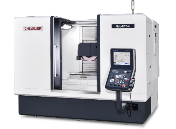
High Efficiency Traveling Column Precision Profile Grinder_FMG-B1224AWC
Automatic diamond roller change module
Automatic wheel change module
The YCM UV650 5-axis vertical machining center provides excellent cutting performance and high accuracy for simultaneous 5-axis application with just one setup. Designed to reduce part handling, setup and overall lead-time, while improving part quality, precision and surface finish of complex shapes and contours required for multiple industries such as job shop, medical, aerospace, and die & mold.
For more information on YCM's products and solutions, please visit:
Website: https://www.YCMCNC.com/en
Facebook: https://www.facebook.com/YCMCNCMACHINE/
Twitter: https://twitter.com/YCMCNCMACHINE
LinkedIn: https://www.linkedin.com/company/ycmcncmachine
Instagram: https://www.instagram.com/ycmcncmachine/
The wind turbines have grown in size in both height and blade lengths and generate more energy.
The casting workpiece processing is a challenge for the maker to handle the production.
Honor PL-600CM Intelligent Vertical Turning Center is the high-rigid vertical lathe based on the gantry-type with a Y-axis mechanism, and collects multi-functions that can cover the processing requirements by the vertical lathe, the gantry-type machine, and even the horizontal machining center at the same time to achieve done in 1 requirement.
● Champion of Taiwan
- 6-meter table turning center
- Extremely outstanding wind power solution
- Digital-twin technology applied
More efficient, better quality, this is HONOR SEIKI delivers our solutions.
Tongtai has completed hardware , software and service to support our customers to plan from single machine to the production lines , also integrate cross-brands devices. In the other hand, we will use digital-twin to assist the production line planning to decrease the risk of design change. It could also simulate the machining before real processing to optimize the production efficiency.



















We use cookies to optimize and continuously update it according to your needs.The settings can be changed at any time under "Privacy"